Upgrading the Network
In a Node+0 scenario, the only active device between the headend and the customer is the unit that converts the light to RF, thus providing the best possible scenario for network reliability.
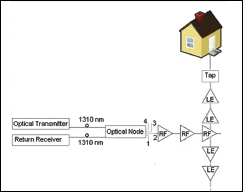 |
| FIGURE 1: Traditional HFC System Node+5 |
A device to convert the light to RF, or a node, will need to be built in such a manner that it can plug into the existing Line Extender housing and location. This is called a LE-Node. In order to allow for fiber access, new lids will need to be built to provide room for power supplies, batteries and fiber access. This unit will need to be built in three or four different configurations to able to plug directly into the housings that are now installed. The only difference will be the physical size and shape; the electrical specifications and performance will be identical.
| Node+0 Configurations | |||||||||
| Fiber Loss | Power Out | Fibers | Splitter | Output Level | Pump Level | Fiber Amplifier | Return Budget | Return Rec In | Return |
| 2 dB | 20 dBm | 1 | 4 way | 11 dBm | No | 27.5 | -20.5 | Passive | |
| 5 dB | 20 dBm | 2 | 2 way | 11 dBm | No | 28.5 | -21.5 | Passive | |
| 9 dB | 20 dBm | 4 | None | 11 dBm | No | 24 | -17 | Passive | |
| 5 dB | 10 dBm | 1 | 4 way | 11 dBm | 200 mW | PEDFA | 27.2 | -20.2 | Passive |
| 8 dB | 13 dBm | 1 | 4 way | 11 dBm | 317 mW | PEDFA | 27.5 | -20.5 | Passive |
| 10 dB | 15 dBm | 2 | 2 way | 11 dBm | 317 mW | PEDFA | 27 | 20 | Passive |
| 13 dB | 18 dBm | 4 | None | 11 dBm | 317 mW | PEDFA | 27 | -20 | Passive |
| 10 dB | 15 dBm | 1 | 4 way* | 11 dBm | AEDFA | 30 | -23 | Pass/Active | |
| 13 dB | 18 dBm | 1 | 4 way* | 11 dBm | AEDFA | 33 | -26 | Active | |
| 16dB | 21 dBm | 1 | 4 way* | 11 dBm | AEDFA | 36 | -29 | Active |
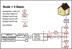 |
| FIGURE2: Node+0 Basic |
In a RF over Glass (RFoG) system, there is an equivalent device on the side of the house, usually referred to as a Network Interface Unit (NIU); in a passive optical network (PON) system, there is an Optical Network Unit (ONU), so by this definition, Node+0 is in the same category. In fact, the argument could be made to call it “HFC PON,” as there will be the same number of active devices in all three.
In configuring such a Node+0 conversion, the goals are to:
• Use the existing fiber and build out fiber from the existing node;
• Replace the existing active node, as much as possible, with a totally passive piece of equipment;
• Utilize the existing coax as a medium for transmission of power to the new LENodes;
• Reduce the power consumption of the new LENodes to a level where economical battery operation would be possible;
• Have optional battery packs in each LENode so that one battery pack could power the LENode while the other was charging, thus effectively disconnecting the LENode from the power grid;
• Provide additional forward bandwidth;
• Provide a method for a future easy increase in reverse bandwidth;
• Provide an easy method where a node could be converted one output at a time; and
• Reduce the number of AC power locations needed for plant powering.
The Demo System
The demo system (Figure 1 on p. 16) is a traditional HFC system with three system amps, perhaps a Gainmaker unbalanced triple, a C-Cor FNT or a Motorola MB. It is assumed that the maximum distance from the optical node to the last LE is 10,000 feet. The demo also just looks at converting line extenders from the last system type amp to a Node+0 configuration.
Power Savings
Because each installation will be different, one only can estimate the actual power savings of a Node+0 installation. Looking at the system shown in Figure 1 and assuming that each system (trunk) amp has four line extenders, that system would use approximately 650 watts of power. Changing the system out to a Node+0 with a passive split or a passive Erbium Doped Fiber Amplifier (PEDFA), and changing all of the 12 line extenders to LENodes, the total power consumption would be 72 watts, translating into a saving of approximately 88 percent.
Taking all installations into account, the power savings should be consistently close to 80 percent. This would equal a savings of more than 5,000 kWh per year and, based on the local rate, would be a savings of as much as $1,200 per year in electrical costs, for just this one node.
There are three different configurations for a Node+0 conversion, based on how far out from the headend the existing optical node is (Figure 2). It is helpful to think of this new system as being similar to a RFoG installation; however, instead of fiber to the home, it will be fiber to the last line extender.
The conversion includes the following elements:
1. Conversion of the transmission system from 1310 nm to 1550 nm;
2. Configuring the return to operate on a single fiber by the addition of WDMs in the headend;
3. Removing the optical and RF portion of the node, leaving only the AC portion active, and replacing it with either:
a. Passive splitters,
b. A Passive EDFA (PEDFA), or
c. An Active EDFA (AEDFA);
4. Running new fiber from the existing optical node to each line extender, either with up to a 32 way splitter (star) or using fiber taps (inline), using a product like CommScope’s BrightPath optical taps or similar; and
5. Replacing each line extender with a new LENode with specifications outlined in Figure 3.
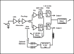 |
| FIGURE 3: LENode Specifications |
| LENode Specifications | ||
| Forward | ||
| Ports | 1 or 2 | |
| Bandwidth | 51-1300 MHz | |
| Input | 0 to -7 dBm @ 1550 nm | |
| C/N | 48* dB | |
| Output | 54/550/1300 MHz | |
| Levels | 35/44/54 dBmV | |
| CTB | 60 dBc | |
| CSO | 58 dBc | |
| XMD | 60 dBc | |
| Reverse 1 Burst Mode Transmitter | ||
| Bandwidth | 5-40 MHz | |
| Optical Out | 7dBm @ 1310 nm | |
| Reverse 2 Burst Mode Transmitter | ||
| Bandwidth | 1600-2600 MHz | |
| Optical Out | 6.5 dBm @ 1610 nm | |
| Power | 6.15 watts (Dual) | |
| Power | 4.3 watts (Single) | |
| *-6 dBm input | ||
Trunk/System Amps
In a conversion, all of the trunk type amplifiers no longer will be used for RF amplifications but the housing will be left in place to provide AC powering to the LENodes. The housing could be removed completely, if provisions are made to continue the AC power.
In Figure 3, the LENode can be configured either with a single or a dual output. It makes more economic sense to use dual outputs where ever possible; however, that will mean the taps on the old input side of the line extender will need to be turned around. In the case of a 2 LE cascade, what is needed is one single and one dual output. With a three-LE cascade, two dual outputs can be used. In some cases, where a feeder line comes off from a system-type amplifier and there are no LEs, on that leg, a single output LENode will need to be added to provide signal for that line. In all cases, the system or trunk amps no longer will be used for RF amplifications, and the housing will be left in place to provide AC powering to the LENodes.
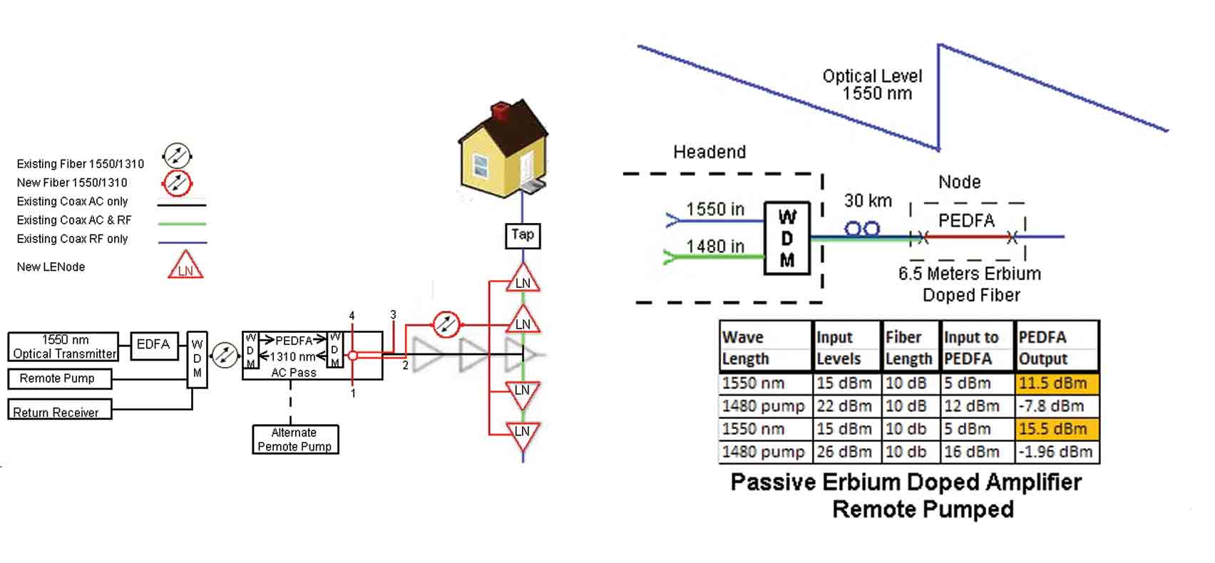 |
| FIGURE 4: Node+0 With PEDFA |
The devices currently available to achieve this design will perform well to 1.3 GHz, resulting in the increase of 300 megahertz in the forward direction. If a second diplex filter is added to the output with a 1.3 GHz forward cutoff and a reverse path of 1.6 GHz to 2.6 GHz, we can build in a future 1 gigahertz of additional reverse bandwidth. The use of 2.6 GHz will require new taps, such as those sold by Javelin Innovations and others; Javelin has a tap that will pass voltage from the tap to the line.
The return laser transmitter will be a burst-mode transmitter, similar to the reverse transmitters used in RFoG installations, but it will operate at a higher level of 7 dBm (5 mW). In some instances, a continuous-on transmitter will be needed or desired, and the transmitters can be converted from burst to continuous by moving a plug-in jumper.
Light Amplification
Many people might assume that the reason for using 1550 nm is the lower loss, as compared with 1310 nm; however, the most prevalent reason for using 1550 nm in the forward direction is the ability to amplify and raise the level of the light going down the fiber. This can be accomplished by using an EDFA. In the system discussed in this article, both PEDFAs and AEDFAs are used to achieve the light levels needed to make the system operate.
This PEDFA is not a new idea; it’s been used for years in undersea submarine systems and is known as Remote Optically Pumped Amplifier (ROPA).
In the discussed solution, at the headend, a 1480 nm pump is combined with the 1550 wavelength, and both will travel down the fiber to the existing node position. In the PEDFA, the SM fiber will be spliced into a 6.5-meter length of Erbium doped fiber; at that point, it will act just like a normal EDFA. This solution is limited by the amount of 1480 nm signal that can be generated and inserted into the downstream fiber and by the fiber loss between the headend and the PEDFA.
Figure 2 notes the amount of launch power and the resultant gain. A 1480 nm is used as a pump wavelength because 980 nm would be attenuated excessively in the fiber and because an EDFA is more efficient with a 1480 nm pump. A good rule of thumb is that an EDFA with a 1480 nm pump will have an output approximately 1 dB lower that the pump power, while an EDFA with a 980 nm pump will have an output approximately 3 dB lower that the pump power.
As the 1480 nm wavelength is passed through the fiber with the 1550 nm wavelength, there will be some Raman amplification. This will decrease the amount of 1550 nm power that must be inserted into the fiber to arrive at the desired 5 dBm input, but it has not been factored into the calculations at this time. By using this solution, the device in Figure 4amplifies the 1550 nm wavelength as a totally passive unit, thus minimizing (if not eliminating) power-related outages. As Figure 3 shows, the more available fibers, the farther the PEDFA can be located from the headend. Most locations should have at least two available fibers.
One of the major drawbacks to the remote 1480 nm pump solution is the relatively high cost and lower power of 1480 nm pump diodes and, because of the attenuation, the relatively low output power achieved at the PEDFA.
Another possible solution would be to have dual external pumps located near or at the PEDFA location and running on battery power. The connection to the PEDFA would be by fiber and ground currents, and their resulting problems could be minimized.
Because of the low power requirements of the LENode, each one can have its own dual battery supply. To power a dual LENode, a battery capable of 10 amp hours at 5 volts is needed; one option could be to alternate the battery packs every eight hours. This level of powering can be achieved with two 5-battery packs of 12,000 mAh of NiMH batteries. By powering the LENode in this manner, it will be disconnected from the power grid, and outages caused by power surges should be eliminated. Unfortunately, lightning strikes to the cable near the LENode probably still could do some damage. The battery packs will have a life of 1,000 cycles, so they will need to be changed out annually.
The use of batteries will increase the annual cost of operation, but it will greatly increase service reliability. An analysis will need to be made comparing the increased reliability to the cost of service calls and the increased annual operating cost of replacing the battery packs. In addition, there is a huge amount of ongoing research on rechargeable batteries, and new and better battery packs are almost a certainty.
Constraints
Once the system gets to 13 dB or 40 kilometers, it will become impossible to use a PEDFA. Instead, an AEDFA or an externally pumped EDFA must be used. In addition, at about the 40-kilometer distance, the return optical loss will be excessive, requiring a return receiver and re-transmitter (Figure 5).
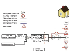 |
| FIGURE 5: Node+0 With AEDFA |
Battery power for the pump lasers in an AEDFA will be a little more challenging, but not impossible. Because the AEDFAs normally will be situated at the old node location, with a standby AC power supply, power should not be a problem. In the case where that high power may not be available, such as in a new build, it is possible to build an EDFA with a 17dBm output that only draws 3 watts. This is a little low for four outputs at 11 dBm; however, by utilizing dual EDFAs or backing off between 1 dB and 2 dB on the system design, this too could be accomplished.
However, the return receiver and re-transmitter on could be run on battery power, like the LENode, for maximum survivability. An eight-channel receiver and dual transmitter will draw a little more than six watts.
| Financial | Operational |
| Lower operational cost due to reduced power | Higher reliability due to reduced active devices |
| Additional future revenue due to increased forward bandwidth | Higher reliability due to less interaction with the power grid |
| Additional future revenue due to increased reverse bandwidth | Forward and reverse sweeping requirements will be eliminated |
| Forward and reverse sweeping costs will be eliminated | Insightful marketing could depict it as a type of a Passive Optical Network (PON) |
| Cost to implement would be much lower than other alternatives | For the financial community, it would still be perceived as a HFC network |
| Lower operational cost due to reduced service calls | Can be implemented, as needed, on a node-by-node basis |
The typical AC power supply currently used in the cable plant works best at high loads. Once the conversion of a section of plant to Node+0 is accomplished, the power load on its power supply will be significantly lower, and this AC power supply should be combined with other adjacent power-supply locations. This should further reduce the power consumption, making it possible to add propane-powered generators to these new central AC locations that now will power a much larger portion of the cable plant. This will also increase the reliability of the system
The Actual Conversion
To actually implement the Node+0 application, it will be necessary to have a temporary AEDFA unit installed at the node location with an additional fiber tap. This will allow the incoming fiber to be split to provide light to the existing node and to allow it to continue operation while the conversation is in progress. The temporary unit would have four outputs that could be used to convert each line individually to Node+0.
As soon as all lines are active as “fiber only,” then the existing node can be converted to whatever configuration is required and the temporary unit removed and used again in the next location. An AEDFA will be needed at the temporary unit because there may only be one fiber to use for the incoming light, and it will have to provide the correct input light level for the existing node to continue to function until the conversion is complete.
As each individual potential installation is designed, by using CWDM and DWDM, an almost endless variety of segmentation and load balancing is possible.
Other Possibilities
Other considerations and embellishments or expansions of the Node+0 project could include the following:
Powering the LENodes from the customers’ homes. Each home could feed power back toward the node, and the closest power supply (home) would provide the power; this means the built-in battery supply would be required. The power supplied from the home would not be much more than is required by a RFoG NIU. This could be a good option in systems where the coax plant is in bad shape and not a reliable power transport system.
Because of the low power requirements of the LENodes, solar power would be a possible option. This also would require the battery-backup option to be installed. It could work very well in a new build or where the coax plant is not reliable.
Replace the LENodes with PEDFAs, with the reverse pump generated from a subscriber’s home and fed back to the PEDFA with a separate fiber, thus allowing the system to be extended all the way to a RFoG system in the future.
Steven K. Richey is president of 4Cable TV Inc. Contact him at steve@4cable.tv.