DWDM Technology: HFC Networks Reclaim Fiber, Increase Bandwidth
 It is no secret that today’s fiber-optic communication networks are in a state of continual change. Fiber, which was once believed to be the provider of unlimited bandwidth, has been strained in recent years by the explosive growth of the Internet and the proliferation of new applications. Many of the existing hybrid fiber-coaxial (HFC) networks, commonly used by cable operators, were built more than 15 years ago. At that time, between two and eight fibers were allocated for each optical node. This was ample at the time because cable companies primarily were offering broadcast services. Now, subscribers have increased their consumption of high-speed data, high-definition linear digital video, and high-definition video on demand.
At the same time, cable operators are introducing such new and advanced personalized services as multiscreen, network personal video recording and switched digital video (SDV). This calls for greater amounts of bandwidth per subscriber, leaving MSOs scrambling for creative ways to upgrade their existing HFC networks without breaking the bank. In the recent past, cablecos have proposed different techniques to increase the available bandwidth per subscriber, including replacing analog channels with more bandwidth-efficient digital channels or offering switched digital video. These solutions increase the available bandwidth and service offering per subscriber, but can only be taken so far. Additional bandwidth per subscriber only can be generated by network segmentation – reducing the number of customers in a serving area increases the available narrowcast bandwidth per customer. Network segmentation requires a keen understanding of the types of traffic on a given network and the path that each type takes.
Additionally, in many instances, there aren’t sufficient fibers to support segmentation or, if adequate fibers are present, they have been used for other revenue-generating services, leading to a fiber scarcity.
As such, a logical way for service providers to increase their bandwidth capacity is to purchase more fiber, but adding fiber to an existing network can be expensive. It is estimated that for every 15 to 20 kilometers of aerial fiber feeding an average of 1,000 homes, the cost for installation ranges between $150,000 and $200,000 ($150 and $200 per home). The cost for underground installs can be even greater. Additionally, installing fiber is time-consuming and often requires the approval of the city and/or county government.
What To Do?
Fiber reclamation is an approach that enables an MSO to use its existing optical-fiber network more efficiently. The standard method is for optical networks to transmit multiple wavelengths on each fiber. This is the most cost-effective way for operators to leverage the fiber in their existing HFC networks. The most common approach to accomplish this is by deploying Dense Wavelength-Division Multiplexing (DWDM). DWDM involves combining closely spaced wavelengths from different laser light sources onto a single optical fiber while each laser is modulated by an independent set of RF signals.
DWDM acts as a virtual method of adding more fibers to an existing network. The deployment of DWDM technology can increase the overall efficiency of a network by enabling as many as 40 separate wavelengths of data to be delivered through one single optical fiber. Consequently, a few fibers can address the current needs of a HFC network as well as support future growth for applications that require more bandwidth.
Fiber Exhaust
DWDM has been used in HFC networks for many years in both the return path and in forward path broadcast and narrowcast architectures. In both of these cases, the RF signal content consists of a small number of QAM carriers. Full-spectrum forward-path RF signals consisting of analog and digital carriers over a full 1 GHz of bandwidth are more challenging to carry due to the larger number of RF carriers and more stringent noise and distortion requirements for the analog carriers.
When several transmitters with different wavelengths, carrying different information, are combined into a single strand of fiber, the end performance will depend on multiple non-linear physical phenomena. These phenomena are stimulated Raman scattering (SRS), four-wave mixing (FWM) and cross-phase modulation (XPM). Each of these non-linearities creates distortion in fiber networks.
In optical fiber, the refractive index varies with instantaneous optical power. In multi-wavelength systems, this leads to crosstalk impairments between such wavelengths as XPM and FWM.
XPM is a function of separation between the wavelengths. XPM impacts the higher RF frequencies and manifests itself as CSO degradation. To mitigate XPM, the channels must have adequate channel separation.
FWM is a third-order effect that leads to the creation of new optical signals that can fall into the channel band of the desired signals.
FWM manifests itself as CNR degradation from the new channels or CSO degradation from a secondary mixing effect. SRS transfers energy from short wavelengths to longer wavelengths and manifests as CSO degradation at low RF frequencies. SRS is a function of launch power and wavelength spacing. Unlike FWM, SRS increases with an increase in channel spacing. Minimizing the launch power and the channel spacing are mitigation effects for SRS.
While complex, these effects are well-understood by cable operators and equipment vendors. Steps can be taken during system design by careful selection of optical wavelengths and power management to minimize or balance these effects but they serve to limit the number of wavelengths, system reach or system performance.
The latest advance in DWDM technology for cable operators is development of full spectrum DWDM transmitters with wavelengths in 1,550-nm region (C-band). The C-band offers low intrinsic fiber loss plus the use of optical amplifiers known as Erbium-doped fiber amplifiers (EDFAs). This is useful because the insertion loss of the passives used for multiplexing and demultiplexing can be compensated for, and the reach of the fiber can be extended with optical amplification. It also is useful when multiple splits are necessary in a passive optical network (PON).
One downside of the C-band is its relatively high chromatic dispersion. Chromatic dispersion is the variation of group velocity with wavelength. Chromatic dispersion is minimized around 1,310 nm and increases as the wavelength increases. With direct modulation, a transmitter’s wavelength will vary slightly (chirp). The distortion that occurs in the optical fiber due to the interaction between chromatic dispersion and chirp manifests itself as composite second order (CSO) distortion.
 |
| Figure 1: Directly modulated 1,550-nm transmitters first were introduced in 2009. |
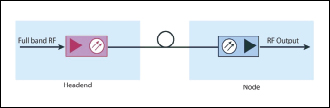 |
| Figure 2: An existing node fed by a directly modulated 1,550-nm transmitter. |
There are multiple ways to solve the issue of chirp plus dispersion. The first one is to use external modulation, where the laser operates in a constant current mode and the actual modulation is performed by an external device connected in series with the laser. External modulation is an effective technique for preventing chirp; however, it is complicated and far more costly than using direct modulation.
A second technique is to use a length of dispersion-compensating fiber to counteract the dispersion in the transmission fiber. However, using dispersion-compensating fiber increases costs, limits the power budget and distances, and increases the non-linear phenomena in the system.
The third technique is electrical predistortion to compensate for the fiber dispersion. Electrical predistortion creates a distortion component of the same amplitude but of opposite phase of the distortion component that would be created in the non-linear event.
In the case of the phenomena of chirp plus dispersion, the amount of distortion is well-defined by the fiber distance and the chirp of the laser. The distortion is known to be quadratic in amplitude with the RF frequency, and its phase is well-defined. Therefore an electrical predistortion technique can be built, in which the distance of propagation needs to be dialed in to compensate for the distortion generated in the fiber.
A Solution That Works
One solution is the directly modulated 1,550-nm transmitter that came about as a result of a dramatic improvement in electronic dispersion compensation across the full CATV RF transmission band, 45 MHz to 1,003 MHz; they are sold by Harmonic and other vendors. Prior to this development, low-cost 1,550-nm transmitters were limited to narrowcast applications with a modest number of quadrature amplitude modulation (QAM) channels only. With the improved dispersion compensation, the requirements of a full-spectrum DWDM transmitter are met: as much as 1 GHz bandwidth, compatibility with optical amplifiers, and linearity suitable for full-band analog and/or digital channel loading.
 |
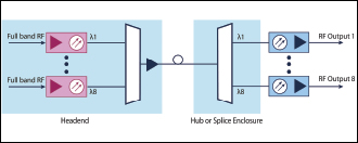
| Figure 3: Directly modulated 1,550-nm transmitters in a 16-wavelength DWDM CATV network. |
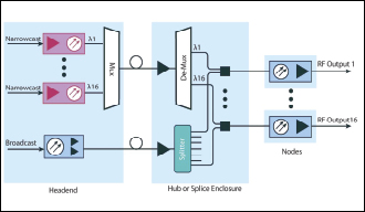 |
| FIGURE 4: Directly modulated 1,550-nm transmitters in a broadcast and narrowcast network. |
Using this, eight wavelengths carrying a full band (50 MHz-1,000 MHz) of analog and digital channels can be transmitted over 40 kilometers with acceptable performance. The wavelengths are first combined and then amplified using an EDFA; they can propagate as much as 40 kilometers before being demultiplexed and sent to individual receivers.
The high chromatic dispersion in the 1,550-nm band helps to mitigate some nonlinear effects. FWM and SRS depend on phase alignment between the co-propagating lightwaves, and high chromatic dispersion destroys the phase alignment and reduces the impacts of FWM and SRS. However, FWM is not completely eliminated, and additional measures must be taken.
Similar to an uneven channel spacing in the RF domain, an uneven channel spacing in the optical domain and controlling the launch power also can be used to mitigate the effects of FWM. The most demanding applications with high analog channel counts require the use of unequally spaced wavelengths and high-performance optical filters, but they are limited to eight wavelengths. As the number of analog channels is reduced, the number of wavelengths can be increased, and systems can be designed using standard DWDM ITU grid passives.
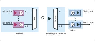
More recent transmitters have been designed for use with lower analog channel counts, standard DWDM ITU grid passives and as many as 16 wavelengths. A 1,550-nm universal transmitter can work as a replacement transmitter for both 1,310-nm and 1,550-nm wavelengths equally well; no modifications are required on the receive side. The lower optical fiber loss at 1,550 nm means 40-percent deeper fiber reach compared to 1,310-nm systems with equal power.
With the addition of multiplexers, demultiplexers and more transmitters, 16 wavelengths can be placed on a single fiber to free it for new services. Networks today were designed for as many as 80 analog carriers, with additional QAM carriers. Already, many operators have transitioned to more digital spectrum, with 30 analog carriers plus 122 QAM, and some have RF loads that already are all-digital. For channel plans with all QAM and no video analog carriers, the relaxed requirements on CSO means that transmission distances can be increased to 70 kilometers.
In the broadcast and narrowcast network, the broadcast transmitter carries the analog and QAM traffic intended for all users, while the narrowcast transmitters carry the QAM information intended for a subset of users. The most common architecture consists of the broadcast and narrowcast signals transported from the headend to the hub via a dedicated fiber for each and then combined in the hub. The advantages of using a directly modulated 1,550-nm transmitter as a narrowcast transmitter include having more than 50 QAM channels today and no risk of short-lived capital investment in a traditional narrowcast transmitter that supports only a modest number of QAM channels.
The main advantage of a fiber-to-the-home (FTTH) network is operational simplicity. No intermediate electronics or powering is necessary between the headend and the subscriber premises. In a FTTH network, one transmitter is shared among multiple subscribers through the use of optical amplifiers and splitters. In some architectures, this transmitter transports only the broadcast video services; in others, it can transport both video and data services. A directly modulated 1,550-nm transmitter is well-suited for this application due to its low cost.
The Future
Full-band DWDM technology currently is available, and MSOs are drawn to its cost-effectiveness, operational simplicity and performance. While the current 8- and 16-wavelength solutions are sufficient for immediate needs, there will be a broader move to help MSOs provide even greater amounts of bandwidth. For example, 32-wavelength technology not only is viable, it’s inevitable. Thirty-two wavelengths over a single fiber is technically demanding, but this emerging solution will help operators stave off obsolescence of their existing networks for years to come.
Gil Katz is vice president/Cable Solutions at Harmonic Inc. Contact him at Gil.Katz@harmonicinc.com.