Common Path Distortion
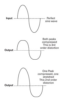
Common path distortion (CPD) is a return path impairment that can have a severe effect on return path signal quality. Although it can take on many forms and degrees of severity, it has a very distinctive signature. It is characterized by a significant rise in the noise floor across the return path spectrum accompanied by beats spaced at 6 MHz intervals, also in the return path. This condition can cause a major reduction in return carrier-to-impairment ratios that can generate errors in digital transmissions. CPD by definition is a distortion. It is a bit of a mystery to some because distortions are typically studied and understood through predictable mathematical formulas and the physics of active devices. CPD is a bit different. It manifests itself in RF connections not normally associated with the generation of distortions. This article will explore the root cause of CPD and its association with distortions that our industry has been dealing with since its inception. This understanding of CPD will assist technicians on how to avoid the condition and identify actions required to minimize its occurrence. Serious impact Under normal conditions, RF connections do not create any signal distortion. It is well understood that when problems do occur in RF connections, signal quality can be seriously compromised, but those problems being abnormal, we tend to concentrate on troubleshooting and repair rather than causality. It is viewed simply as a problem that must be found and fixed. Relative to the major problems that can occur in RF connections, CPD is a minor issue. However, it can have a serious impact on return path signal quality. In many ways, it would be better if the problem were more pronounced because this would make the difficult CPD troubleshooting process much easier. A question that many ask is whether CPD affects forward path signals. The simple answer is yes. Forward path performance tests show that carrier-to-noise ratio (CNR), composite second order (CSO) and composite triple beat (CTB) can degrade in the presence of CPD, but usually not enough to seriously affect picture quality or generate customer complaints. CPD usually affects the return path before becoming a significant forward path problem. As will be explained, the location of the CPD source has a great influence on the nature and magnitude of the CPD effects. An explanation and analysis of the cause of CPD requires a basic understanding of how distortions are created in active devices. Distortions explained Distortions are created by only one thing: Nonlinear transfer characteristics of a device. Linear transfer : Any time a signal passes through a device, as long as the shape of the output signal is identical to the shape of the input signal, amplified or not, the device is considered to be linear. Changes in signal amplitude do not create distortions, only changes in the shape of the waveform. Nonlinear transfer : Any time a signal passes through a device and the shape of the signal from the input to the output is changed, the device is considered to be nonlinear. The type and amount of change relates directly to the amount and type of distortion created. So to summarize, linear devices create no distortion, and nonlinear devices create distortion. Period! Amplifiers used in cable systems are nonlinear and lend themselves well to the analysis of distortions. When amplifiers are operated at or below recommended signal levels, they create little distortion, but are never perfect. Because of the addition of distortions created in amplifier cascades, they have always been the limiting factor regarding RF amplifier output levels and the distance signals can be transported in a cable system. The best way to understand and explain how distortions are created in a nonlinear device is to analyze harmonic distortion. Harmonic distortion is understood best by analyzing a single continuous wave (CW) signal passing through a nonlinear device. This is because no matter how complex a waveform is, it can be recreated by combining a number of CWs at different frequencies, phases and amplitudes. As shown in Figure 1, a CW signal or any waveform will be affected in one of two ways when passed through a nonlinear device designed to operate in a linear fashion. At the output:
- Both the positive and negative peaks will be rounded off (flattened).
- One peak will be expanded (stretched) and the other rounded off (flattened).
 |
|
FIGURE 1: Effects of Passing through a Nonlinear Device
|
Although Figure 1 illustrates second and third order harmonic distortion separately, a real amplifier will exhibit a certain degree of both at the same time. The distorted output signals shown in Figure 1 occur because of only one thing, the nonlinear transfer characteristic (curve) of a device.
A perfect linear amplifier transfer curve is shown in Figure 2. Amplifiers with this transfer characteristic cannot be physically produced. Third-order harmonics Figure 3 shows an exaggerated but typical transfer curve of an amplifier exhibiting third order curvature. The top and bottom peaks at the output are rounded-off because of the nonlinear transfer curve. Now the important concept: As shown in Figure 4, a perfect CW signal added to (combined with) another perfect CW at exactly three times the frequency, yields a waveform that will be a CW at frequency F with both the positive and negative peaks rounded off. Now think of this concept in reverse. If a perfect CW is distorted in a nonlinear device where both peaks are rounded off, another unwanted CW at three times the frequency is actually created. When the unwanted harmonic distortion falls at a frequency where another signal is carried, and has high enough amplitude, it can cause interference. This new, unwanted signal at three times the original frequency is distortion and is called the third harmonic. The more the device distorts the signal, the more both peaks are rounded off, and the higher the amplitude of the harmonic. Second-order harmonics Figure 5 shows an exaggerated but typical transfer curve of an amplifier exhibiting second-order curvature. From the explanation of third-order harmonic distortion, second-order harmonic distortion should be easily understood. The difference lies in how the input waveform is distorted by the device. Second-order distortions are created because the top and bottom of the transfer curve are never perfectly symmetrical, and biasing the input signal in the most linear portion of the device is never perfect. Second-order distortion follows the same concept as third-order distortion. If two perfect CWs are combined at the frequencies and phases as shown in Figure 6, the result is a distorted waveform with one peak stretched and one compressed. Again, think of this concept in reverse. If a perfect CW is distorted in a nonlinear device where one peak is stretched and one compressed, another unwanted CW will be created at two times the frequency. Intermodulation Intermodulation distortions are created by the same condition as harmonic distortions but involve how RF envelopes, created by different carrier combinations, are distorted in a nonlinear device. Intermodulation distortions are of greater concern because third-order and second-order harmonics are 15.6 dB and 6 dB weaker respectively than individual intermodulation distortions. These distortions are commonly referred to as intermodulation beats. To go one step further, individual intermodulation beats are not generally of great concern in a cable system. However, they can become a serious problem when numerous beats created by different carrier combinations “pile up” at certain frequencies. In a typical modern cable system, hundreds of second-order beats and thousands of third-order beats can fall at certain frequencies. The total of all second-order beats and third-order beats that fall at a particular frequency are our old friends CSO and CTB, respectively. The diode effect CPD is commonly referred to as a “diode effect” and is the source of the problem. Anyone who has had to deal with CPD has probably heard this term, but what does it mean? At certain places in the distribution system, carrier combinations create “beats” that fall outside the bandwidth of the cable system and are therefore ignored. In a cable amplifier, the forward hybrids are nonlinear and create many beats that fall in the return spectrum. They are typically not considered because they occur inside the diplex filter locations and can’t enter or affect the return path. “Common path” refers to locations in a cable system where the forward and reverse signals coexist. If forward path signals are distorted in a common path location, beats created that fall in the reverse spectrum can interfere with reverse signals. Beats created by forward path digital signals are the source of the increase in noise. This is the exact source of CPD, forward path signal distortion occurring at a common path location. The very first solid-state rectifying diodes were created by “growing” an oxide layer at a junction in the device. If any connection passing a cable signal corrodes, an oxide layer can develop at the connection and create a tiny diode resulting in a potential source point for CPD. Figure 7 depicts the transfer characteristic of a common diode. As shown, a diode is nonlinear and can create distortion. If this happens outside the diplex filter locations, the forward signals can create beats that fall in the return path spectrum. If a corroded connection creates a diode with the transfer characteristics shown in Figure 7, massive distortions would be created, and both forward and reverse signals would be seriously affected. With CPD, a nonlinear transfer curve is created at the connection, but less pronounced than that of a perfect diode. With CPD, it is called a diode effect because the corrosion distorts signals to a lesser degree than a perfect diode, but for the exact same reasons. The location where this occurs is a major factor in the severity of the effect. Worst case is at or near the output of an amplifier because forward signals are at the highest amplitude, and the return signals are at the lowest. When outside the diplex filter, distortions created by the forward signals but falling in the return path spectrum enter the amplifier’s return section and are further amplified by the return hybrid. The severity of the CPD is typically associated with the distance of the condition from the forward output of an amplifier. Cable connectors are not the only potential source of CPD. Be mindful of amplifier module-to-housing G-connectors, plug-in passives and terminators; never clean a connector with an abrasive material—this can actually promote the condition. Summary It has been shown that the severity and unpredictability of CPD is associated with:
- The degree to which a connector corrodes and simulates the junction of a diode
- The distance between the corroded connecter and forward output of an amplifier
- The magnitude of both the forward and reverse signals at the CPD source
The solution to preventing CPD is simple. Keep all connections from corroding. In reality, that’s difficult because:
- There are so many locations where this can happen that it’s bound to occur.
- Moisture shouldn’t enter these locations, but sometimes does and corrodes connections.
- Moisture can enter connections when technicians open a housing or splicing is preformed in non-ideal weather conditions.
- The corrosion process can start before installation if parts are exposed to moisture or high humidity conditions over extended periods.
Even though we can never completely eliminate all conditions that create CPD, we can be more mindful of the conditions that create it and take steps in our daily activities to avoid it. So in conclusion, keep those connectors clean, dry and protected to save yourself a lot of time and aggravation.
Ronald Mesavage is district training engineer for Bresnan Communications. Reach him at rmesavage@bresnan.com.