The FTTx Factor:
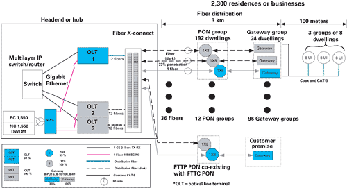
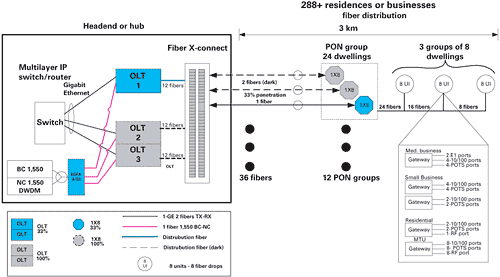
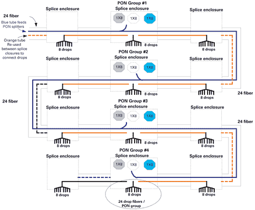
In a metropolitan area environment, you want to deploy a network that can scale with subscriber penetration while minimizing initial capital expenditures. While point-to-point fiber topologies promote scalability of electronics, the thousands of fiber pairs and the associated termination costs to serve a relatively small geographic area make the topology less than attractive when looking at the physical layer costs as compared to a passive optical network (PON) topology. Options include deploying fiber-to-the-curb (FTTC) to start, then ultimately delivering fiber to the end user. Or they may be simultaneously integrated utilizing the same platform to meet disparate end-user service requirements. FTTC defined As an example of FTTC, it could provide you with a passive fiber network between the headend or hub and a group of 24 subscribers with each fiber eventually serving eight subscribers. This FTTC solution would place a single fiber-optic cable near the end-user in scalable groups of 24 dwellings. In each 24-home or -business group, up to three eight-port terminal devices can be placed based on subscriber penetration. Coaxial cable for RF cable services and copper pairs for Internet protocol (IP) Ethernet and telephony services are positioned in the final 100 meters to the end users. Another option includes extending the fiber passive network all the way to the customer premises or end user. This is fiber-to-the premises (FTTP). As an example, the FTTP solution could place fiber-optic 1×8 passive optical splitters in scalable groups of 24 dwellings. A single fiber would extend from the group of splitters directly to the end user and terminate at each user with a selection of terminal devices. Figure 1 depicts a last mile link (LML) FTTC topology and equipment that initially would provide service to 2,300 dwellings. The equipment needed and supporting infrastructure is simply duplicated for a larger serving area. To provide subscriber services, the optical line terminal (OLT) interfaces with a multilayer gigabit Ethernet (GigE) switch/router within the headend or hub, via GigE optical interfaces for telephony, T1/E1 and IP services. For RF services, the OLT interfaces with standard 1,550 nm cable transmission equipment. Multiple wavelengths may be transmitted through the system utilizing a set wavelength for the broadcast signals and dense wavelength division multiplexing (DWDM) wavelengths for the narrowcast video signals that may be targeted to a specific user group. This configuration allows for all of the LML components, GigE switch router blades, OLT chassis and PON modules, 1×8 passive splitters, and gateways to be deployed incrementally with subscriber penetration. From the headend to the client, you can establish three points within the distribution network where the network components and subscriber connections are scaled as subscriber penetration increases. Here’s an example: PON group: This could consist of three 1×8 optical splitters connected back to the PON ports of the OLT. Each 1×8 splitter is incrementally placed to match subscriber penetration. Each PON group location serves up to 192 dwellings or subscribers. Gateway group: This consists of a group of gateways each connected to a single port on the 1 x 8 optical splitters at the PON group location. Each gateway is placed incrementally along with the PON splitters to match subscriber penetration. Network termination: This provides a connection point for the transition from network cables to the cabling inside the client’s home or business. Each location serves eight dwellings or subscribers. In this example, each location is set up to be scalable in 33 percent increments. For flexibility, the actual deployment could be optimized to scale in larger or smaller equipment groupings to suit best the dynamics of the service area. In any case, the point is, the network can be built to minimize the upfront cost of deployment by distributing the points of network scalability as compared to a dedicated fiber solution. In Figure 1, we have placed three 1×8 optical splitters at each PON group, which are placed incrementally as needed to match the subscriber penetration. The first 1×8 splitter deployed provides service for up to 33 percent penetration. Each PON location serves up to 192 dwellings or subscribers with three 1×8 optical splitters. The PON location can be established within a splitter/splice enclosure or cabinet to match the desired location, whether in the street, building or telephone pole. Each port of the 1×8 optical splitter connects to a gateway positioned at the group location. Gateway group Up to three gateways are placed to establish a 24-dwelling or -subscriber serving area. The gateways may be placed in the network up to 5 km from the OLT and within 100 meters of the clients’ appliances to maintain the 100-meter Ethernet standard for CAT-5 cabling. The gateway provides the optical termination for connection to the clients via coaxial cable. Each gateway provides eight RF ports, eight 10/100BaseT ports and eight plain old telephone service (POTS) ports, and is placed incrementally according to subscriber penetration. Powering can come from a local power supply or a centralized power supply via existing coax cable in a hybrid fiber/coax (HFC) upgrade scenario. The gateway could operate over a -40� to +60�C temperature range and may be placed in a street, pedestal or wall-mounted cabinet. Coax is placed in the last 100 meters of the network to the subscribers’ termination equipment. The gateway group location is subdivided into three eight-sub network termination groups. So any one subscriber within a group of eight may be activated on the first deployed gateway. When the first eight ports are populated on a gateway, a second is activated. Furthermore, the scalability can be achieved on a per-service basis as well. For example, if a customer only subscribes to video service, you can use the data and telephone ports for another subscriber because each is independently provisioned. In this example, the gateway can support eight video, eight data and eight telephony customers independently or any combination of services on a per subscriber basis. Network termination Network termination provides a final connection point to transition to the cables entering each dwelling. It may be desirable to place a multipair and coax bundled in a single cable between the gateway group and network termination group. The location serves a splice point between the bundled cable and the client’s internal cables. You also may want to place PONs dedicated to serve customers directly with fiber for higher dedicated bandwidth or special circuit requirements such as E1 or T1 service. For these cases, fiber is placed directly from the PON split to the client and terminated with the gateway. The dedicated FTTP PONs utilize the same OLT ports that are serving the FTTC network. FTTP at work FTTP can provide a very scalable and entirely passive solution between the headend or hub and the customer premise. This offers the least intrusive network possible in terms of civil disruption in a metropolitan deployment and eliminates network powering of the gateway subscriber terminal devices. Figure 2 depicts an FTTP topology and equipment to initially provide service to 288 or more dwellings depending on the number of multitenant units (MTUs) that are served with the gateway as in the FTTC topology. The equipment needed and supporting infrastructure simply is duplicated for a larger serving area. Services within the headend can be provided in the same manner as the FTTC topology. In this example, the equipment is the same and may be utilized for FTTP and FTTC applications simultaneously. The network configuration allows for all of the OLT components, GigE switch router blades, chassis and PON modules, and splice enclosures or 1×8 passive splitters to be deployed incrementally with increased subscriber penetration. From the headend to the client, you can establish two points within the distribution network enabling the network components and subscriber connections to be scaled as subscriber penetration increases: PON group: The PON location consists of a group of three 1×8 optical splitters connected back to the PON ports of the OLT. Each 1×8 splitter is incrementally placed to match subscriber penetration. Each PON location serves up to 24 dwellings or more depending on the mix of MTU dwellings served with the gateway. Network termination: This could provide a connection point for the transition from network cables to the cabling inside the client’s home or business. Each location could serve eight dwellings or subscribers in our example. As in the FTTC topology, each location is set up to be scalable in 33 percent increments. For flexibility, the actual deployment can be optimized in larger or smaller equipment groupings to best suit the dynamics of the service area. The OLT is located in the headend, or may be remotely placed up to 70 km from the switch. Each set of OLT modules establishes 12 1×8 optical PONs for a total of 96 optical ports, which are terminated by the gateway terminal device located at the subscriber premises. Different physical configurations of OLTs are available. For example, there is a field-hardened cast aluminum enclosure and a rackmount chassis for indoor or street cabinet mounting. The network side connection to the OLT can be a standard GigE single-mode optical interface connected to a router to aggregate the multiple GigE connections. The network side interface module in the OLT is called the CMM, core main module. As subscriber penetration increases, OLTs and GigE interfaces on the switch/router can be added as needed as subscriber penetration increases. A fiber cross-connect or patch panel can be placed between the OLTs and the outside plant cables feeding the PON groups to facilitate the activation of PON ports as needed based on subscriber penetration. Three fibers are needed to each PON location to ultimately support 100 percent subscriber penetration. All fibers initially could be placed with one fiber activated and two dark fibers to be activated with each 33 percent penetration increment. Other fiber placement techniques may be utilized such as placing fiber duct and utilizing blown fiber installation as needed. In Figure 2, we have placed three 1×8 optical splitters at each PON location, which are incrementally installed as needed to match the subscriber penetration as in the FTTC topology. The first 1×8 splitter deployed provides service for up to 33 percent penetration. Each PON location serves up to 24 dwellings or subscribers with three 1×8 optical splitters. The PON location can be established within a splitter/splice enclosure or cabinet to match the desired location weather in the street, building or telephone pole. Fibers are placed between the PON group and network termination location allowing subs within the 24-unit group to be connected to the optical 1×8 splitters. Network termination The network termination provides a final connection point to transition from the network fiber cable to the fiber cables entering each dwelling or a point to place a gateway if coax will enter the premises. It may be desirable to place a multiple fiber cable between the PON group and each termination point. For example, from the PON group, a 12-count fiber cable may be placed to a termination splice box to accommodate eight individual subscribers. The termination box then would provide a splice point between the bundled cable and each client’s internal fiber cable. Multiple PON groups and termination locations may be positioned along the same fiber route. Figure 3 provides an example of feeding a group of 96 end points with a single 24-count fiber cable. The fiber may extend from the cable termination point into the client’s premises and then be terminated with a gateway. Several flexible choices exist to meet the needs of your subscribers. Paul Whittlesey is vice president of product marketing at Wave7 Optics. Reach him at paul.whittlesey@w7optics.com. Did this article help you? Send comments to lhamilton@accessintel.com. Bottom Line Flexible Fiber Cable operators need flexible fiber deployment options that reduce startup costs while removing deployment barriers associated with an unmanageable fiber infrastructure. An FTTP solution can provide up to a 24 times reduction in the amount of fiber, and an FTTC topology reduces the amount of fiber by more than 100 times as compared to a central point-to-point topology. With a combined network splicing and fiber termination costs that approach $100 per fiber, topologies exist that provide a cost-effective solution that enables you to engage in the deployment of an all-fiber-based topology today. 

